FAR Overview
Feature Adaptive Representation (Far)
XXXX <need broader description of Far here -- more than just TopologyRefiner>
The Far classes package up the functionality provided in Vtr for public use, either directly within Far or indirectly eventually though Osd. The two classes classes are as follows:
XXXX <is the intent to extend this table to include other classes?>
| TopologyRefiner | A class encapsulating the topology of a refined mesh. |
| TopologyRefinerFactory<MESH> | A factory class template specialized by users (in terms of their mesh class) to construct TopologyRefiner as quickly as possible. |
These classes are the least well defined of the API, but given they provide the public interface to all of the improvements proposed, they potentially warrant the most attention. Far::TopologyRefiner is purely topological and it is the backbone used to construct or be associated with the other table classes in Far.
Alpha Issues
Interface issues needing attention:
- TopologyRefiner::Refine() needs more options (bundled in struct)
- TopologyRefiner::Interpolate() methods need revisiting
- considering simplifying TopologyRefiner interface overall -- may expose TopologyLevel for public inspection
- specialization of TopologyRefinerFactory<MESH> needs more work
Refining Topology
XXXX <insert blurb about uniform / adaptive refinement>
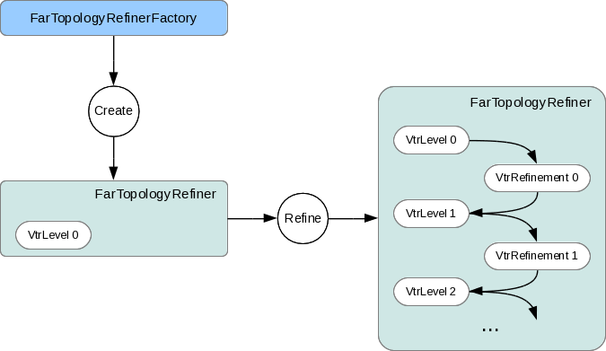
Far::TopologyRefiner
TopologyRefiner is the building block for many other useful classes in OpenSubdiv, but its purpose is more specific. It is intended to store the topology of an arbitrarily refined subdivision hierarchy to support the construction of stencil tables, patch tables, etc.
Aside from public access to topology, TopologyRefiner::Refine(...) is internally where simple specifications of refinement (currently uniform or feature-adaptive with a level argument) will be translated into refinement operations within Vtr. Feature-adaptive refinement is a special case of "sparse" or "selective" refinement, and so the feature-adaptive logic exists internal to TopologyRefiner and translates the feature-analysis into a simpler topological specification of refinement to Vtr.
The longer term intent is that the public Refine(...) operation eventually be overloaded to allow clients more selective control of refinement. While TopologyRefiner is a purely topological class, and so free of any definitions of vertex data, the public inteface has been extended to include templated functors that allow clients to interpolate primitive variable data.
Far::TopologyRefinerFactory
Consistent with other classes in Far instances of TopologyRefiner are created by a factory class -- in this case Far::TopologyRefinerFactory. This class is an important entry point for clients its task is to map/convert data in a client's mesh into the internal Vtr representation as quickly as possible.
The TopologyRefinerFactory class is a class template parameterized by and specialized for the client's mesh class, i.e. TopologyRefinerFactory<MESH>. Since a client' mesh representation knows best how to identify the topological neighborhoods required, no generic implementation would provide the most direct means of conversion possible, and so we rely on specialization. For situations where mesh data is not defined in a boundary representation, a simple container for raw mesh data is provided along with a Factory specialized to construct TopologyRefiners from it.
So there are two ways to create TopologyRefiners:
- use the existing TopologyRefinerFactory<TopologyDescriptor> with a populated instance of TopologyDescriptor
- specialize TopologyRefinerFactory<class MESH> for more efficient conversion
XXXX <insert blurb about Descriptor>
Specialization of TopologyRefinerFactory<class MESH> should be done with care as the goal here is to maximize the performance of the conversion and so minimize overhead due to runtime validation. The template provides the high-level construction of the required topology vectors of the underlying Vtr, with the requirement that two methods will be specialized with the following purpose:
- specify the sizes of topological data so that vectors can be pre-allocated
- assign the topological data to the newly allocated vectors
As noted above, the assumption here is that the client's boundary-rep knows best how to retrieve the data that we require most efficiently. After the factory class gathers sizing information and allocates appropriate memory, the factory provides the client with locations of the appropriate tables to be populated (using the same Array classes and interface used to access the tables). The client is expected to load a complete topological description along with additional optional data, i.e.:
- the six topological relations required by Vtr, oriented when manifold
- sharpness values for edges and/or vertices (optional)
- additional tags related to the components, e.g. holes (optional)
- values-per-face for face-varying channels (optional)
While there is plenty of opportunity for user error here, that is no different from any other conversion process. Given that Far controls the construction process through the Factory class, we do have ample opportunity to insert runtime validation, and to vary that level of validation at any time on an instance of the Factory.
A common base class has been created for the factory class, i.e.:
template <class MESH>
class TopologyRefinerFactory : public TopologyRefinerFactoryBase
both to provide common code independent of <MESH> and also potentially to protect core code from unwanted specialization.
Patch Tables
Content under development....

Stencil Tables
Content under development....
The base container for stencil data is the StencilTables class. As with most other Far entities, it has an associated StencilTablesFactory that requires a TopologyRefiner:
Principles
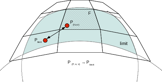
Iterative subdivision algorithms such as the one used in SubdivisionTables converge towards the limit surface by sucessively refining the vertices of the coarse control cage.
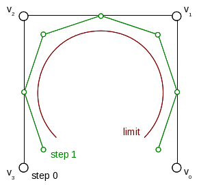
Each step is dependent upon the previous subidivion step being completed, and a substantial number of steps may be required in order approximate the limit. Since each subdivision step incurs an O(4 n) growing amount of computations, the accrued number of interpolations can be quite large.
However, every intermediate subdivided vertex can be expressed as a linear interpolation of vertice from the previous step. So, eventually, every point at on the limit surface can be expressed as a weighted average of the set of coarse control vertices from the one-ring surrounding the face that the point is in:
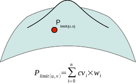
Where:
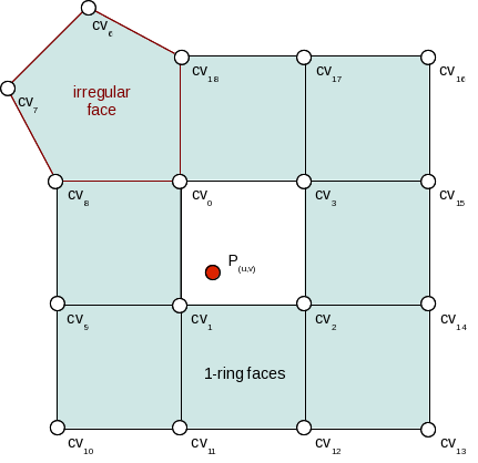
Stencils are created by combining the list of control vertices of the 1-ring to a set of interpolation weights obtained by successive accumulation of subdivision interpolation weights.
The weight accumulation process is made efficient by adaptively subdividing the control cage only around extraordinary locations, and otherwise reverting to fast bi-cubic bspline patch evaluation. The use of bi-cubic patches also allows the accumulation of analytical derivatives.
Limit Stencils
Limit stencils are the most direct method of evaluation of specific locations on the limit of a subdivision surface starting from the coarse vertices of the control cage.
Sample Location
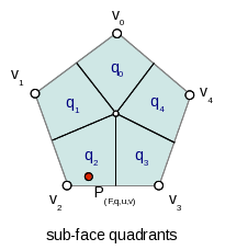
Each stencil is associated with a singular parametric location on the coarse mesh. The paramatric location is defined as face location and local [0.0 - 1.0] (u,v) triplet:
In the case of a non-coarse quad face, the parametric sub-face quadrant needs to be identified. This can be done either explicitly or implicitly by using the unique ptex face indices for instance.
Code example
When the control vertices (controlPoints) move in space, the limit locations can be very efficiently recomputed simply by applying the blending weights to the series of coarse control vertices:
class StencilType {
public:

    void Clear() {
        memset( &x, 0, sizeof(StencilType));
    }

    void AddWithWeight( StencilType const & cv, float weight  ) {
        x += cv.x * weight;
        y += cv.y * weight;
        z += cv.z * weight;
    }

    float x,y,z;
};

std::vector<StencilType> controlPoints,
                         points,
                         utan,
                         vtan;

// Uppdate points by applying stencils
controlStencils.UpdateValues<StencilType>( reinterpret_cast<StencilType const *>(
    &controlPoints[0]), &points[0] );

// Uppdate tangents by applying derivative stencils
controlStencils.UpdateDerivs<StencilType>( reinterpret_cast<StencilType const *>(
    &controlPoints[0]), &utan[0], &vtan[0] );