Subdivision Compatibility
Subdivision Compatibility
This document highlights areas of compatibility with other software that makes use of subdivision surfaces, including previous versions of OpenSubdiv.
The "compatibility" here refers to the choice of subdivision rules that define the shape of the resulting surfaces. Different subdivision rules will lead to different shapes. Choices affecting shape include:
- the types of subdivision schemes supported (e.g. Catmull-Clark, Loop, etc.)
- the basic rules applied for these schemes
- any extended rules to affect sharpness or creasing
- rules applied separately to face-varying data
Ensuring all of these rules are consistent provides the basis for consistent shapes, but further approximations to the limit surface create the potential for subtle deviations. Even within OpenSubdiv, multiple approximations are possible and vary. For now we focus on the compatibility of subdivision rules and deal with the limit approximations only when noteworthy.
Compatibility with OpenSubdiv 2.x
The refactoring of OpenSubdiv 3.0 data representations presented a unique opportunity to revisit some corners of the subdivision specification and remove or update some legacy features.
Face-varying Interpolation Options
Face-varying interpolation options have been consolidated into a single enum with one additional choice new to 3.0. No functionality from 2.x has been removed -- just re-expressed in a simpler and more comprehensible form.
Face-varying interpolation was previously defined by a "boundary interpolation" enum with four modes and an additional boolean "propagate corners" option, which was little understood, i.e.:
- void HbrMesh::SetFVarInterpolateBoundarMethod(InterpolateBoundaryMethod) const;
- void HbrMesh::SetFVarPropagateCorners(bool) const;
The latter was only used in conjunction with one of the four modes ("edge and corner"), so it was effectively a unique fifth choice. Closer inspection of all of these modes also revealed some unexpected and undesirable behavior in some common cases -- to an extent that could not simply be changed -- and so an additional mode was added to avoid such behavior.
All choices are now provided through a single "linear interpolation" enum, described and illustrated in more detail in the overview of Face-Varying Interpolation. The use of "boundary" in the name of the enum was intentionally removed as the choice also affects interior interpolation. The new use of "linear" is now intended to reflect the fact that interpolation is constrained to be linear where specified by the choice applied.
All five of Hbr's original modes of face-varying interpolation are supported (with minor modifications where Hbr was found to be incorrect in the presence of semi-sharp creasing). An additional mode ("corners only") has also been added to avoid some of the undesired side-effects of some existing modes (illustrated below).
The new values for the "Sdc::Options::FVarLinearInterpolation" enum and its equivalents for HbrMesh's InterpolateBoundaryMethod and PropagateCorners flag are as follows (ordered such that the set of linear constraints applied is always increasing -- from completely smooth to completely linear):
| Sdc FVarLinearInterpolation | Hbr FVarInterpolateBoundaryMethod | Hbr FVarPropogateCorners |
|---|---|---|
| FVAR_LINEAR_NONE | k_InterpolateBoundaryEdgeOnly | N/A (ignored) |
| FVAR_LINEAR_CORNERS_ONLY | N/A | N/A |
| FVAR_LINEAR_CORNERS_PLUS1 | k_InterpolateBoundaryEdgeAndCorner | false |
| FVAR_LINEAR_CORNERS_PLUS2 | k_InterpolateBoundaryEdgeAndCorner | true |
| FVAR_LINEAR_BOUNDARIES | k_InterpolateBoundaryAlwaysSharp | N/A (ignored) |
| FVAR_LINEAR_ALL | k_InterpolateBoundaryNone | N/A (ignored) |
Aside from the two "corners plus" modes that preserve Hbr behavior, all other modes are designed so that the interpolation of a disjoint face-varying region is not affected by changes to other regions that may share the same vertex. So the behavior of a disjoint region should be well understood and predictable when looking at it in isolation (e.g. with "corners only" one would expect to see linear constraints applied where there are topological corners or infinitely sharp creasing applied within the region, and nowhere else).
This is not true of the "plus" modes, and they are named to reflect the fact that more is taken into account where disjoint regions meet.
The following example illustrates some undesired effects of the "plus" modes, which in part motivated the addition of the new "corners only" mode. The example uses the "catmark_fvar_bound0" and "catmark_fvar_bound1" shapes from the suite of regression shapes. Both shapes are a simple regular 4x4 grid of quads with face-varying UV data partitioned into multiple disjoint regions. The "bound0" shape has two disjoint UV regions -- an upper and lower region -- while the "bound1" shape further splits the lower region in two.
This first figure illustrates the effect of the original "plus1" mode (which is also the same for "plus2"):
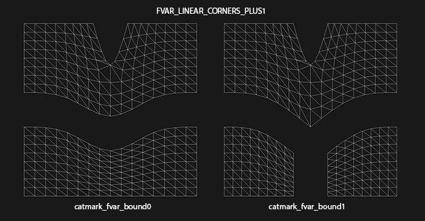
Note that the effect of splitting the lower UV region in two has the undesired side effect of sharpening the boundary of the upper region. This is the result of the "plus1" mode making collective decisions about the sharpness of all face-varying boundaries at the vertex rather than decisions local to each region. In both the "plus1" and "plus2" cases, all face-varying boundaries sharing a vertex will be sharpened if there are more than two regions meeting at that vertex.
The second figure illustrates the effect of the new "corners only" mode:

As expected, the splitting of the lower region does not impact the upper region. In this case the decision to sharpen a face-varying boundary is made based on the local topology of each region.
Vertex Interpolation Options
Since the various options are now presented through a new API (Sdc rather than Hbr), based on the history of some of these options and input from interested parties, the following changes have been implemented:
- The naming of the standard creasing method has been changed from Normal to Uniform. Values for "Sdc::Options::CreasingMethod" are now:
| CREASE_UNIFORM | standard integer subtraction per level (default) |
| CREASE_CHAIKIN | Chaikin (non-uniform) averaging around vertices |
- Legacy modes of the "smoothtriangle" rule have been removed (as they were never actually enabled in the code). Values for "Sdc::Options::TriangleSubdivision" are now:
| TRI_SUB_CATMARK | Catmull-Clark weights (default) |
| TRI_SUB_SMOOTH | "smooth triangle" weights |
These should have little impact since one is a simple change in terminology as part of a new API while the other was removal of an option that was never used.
Change to Chaikin creasing method
In the process of re-implementing the Chaikin creasing method, observations lead to a conscious choice to change the behavior of Chaikin creasing in the presence of infinitely sharp edges (most noticeable at boundaries).
Previously, the inclusion of infinite sharpness values in the Chaikin method's computation of edge sharpness around a vertex would prevent a semi-sharp edge from decaying to zero. Infinitely sharp edges are now excluded from the Chaikin (non-uniform) averaging yielding a much more predictable and desirable result. For example, where the sharpness assignment is actually uniform at such a vertex, the result will now behave the same as the Uniform method.
Since this feature has received little use (only recently activated in RenderMan), now seemed the best time to make the change before more widespread adoption.
Hierarchical Edits
While extremely powerful, Hierarchical Edits come with additional maintenance and implementation complexity. Support for them in popular interchange formats and major DCC applications has either been dropped or was never implemented. As a result, the need for Hierarchical Edits is too limited to justify the cost and support for them, and they have therefore been removed from the 3.0 release of OpenSubdiv. Dropping support for Hierarchical Edits allows for significant simplifications of many areas of the subdivision algorithms.
While the 3.0 release does not offer direct support for Hierarchical Edits, the architectural changes and direction of 3.0 still facilitate the application of the most common value edits for those wishing to use them -- though not always in the same optimized context. Of course, support for Hierarchical Edits in the future will be considered based on demand and resources.
Non-Manifold Topology
OpenSubdiv 2.x and earlier was limited to dealing with meshes whose topology was manifold -- a limitation imposed by the use of Hbr. With 3.0 no longer using Hbr, the manifold restriction has also been removed.
OpenSubdiv 3.0, therefore, supports a superset of the meshes supported by 2.x and earlier versions (with one known exception noted below).
Non-manifold meshes that are acceptable to 3.0 however will likely not work with 2.x or earlier.
The one known case that 3.0 will not represent the same as 2.x is ironically a case that is non-manifold, and for which Hbr did make special accommodation.
That case occurs at a non-manifold vertex where two or more faces meet at a common vertex, but do not share a common edge, and when the boundary interpolation mode is set for smooth corners (i.e. "edge only"), as illustrated below:
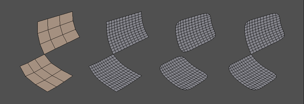
The cage is on the left and is refined to level 2 on the right. On the immediate right, boundary interpolation is set to sharp corners and the results appear the same for 2.x and 3.0. The center and far right illustrate the affects of setting boundary interpolation to smooth corners with 2.x and 3.0 respectively. Note that the 2.x result allows the refined mesh (and so the limit surface) to split into two while the 3.0 result keeps it connected.
When Hbr encounters such vertices, regardless of the boundary mode it "splits" the vertex -- creating a separate instance of it for each face. So when building an HbrMesh, after "finalizing" the mesh, it will result in having more vertices than were originally defined (termed "split vertices").
OpenSubdiv 2.x (and earlier) successfully hid the presence of these extra vertices from users.
This case behaves in such a way that violates certain properties of the surface that 3.0 has attempted to emphasize. One of these relates to the nature of the limit surface (and becomes more significant in the context of face varying): if the cage is connected then so too is its limit surface, or similarly, if the cage consists of N connected regions then the limit surface similarly consists of N connected regions. Another undesirable property here is that the vertex V at which these faces meet must have more than one child vertex V'. This makes it difficult to "hide" split vertices -- OpenSubdiv 2.x tables had an extra level of indirection that made it possible to do this relatively easily, but 3.0 has dispensed with such indirection where possible to streamline performance.
Compatibility with RenderMan
Since RenderMan and OpenSubdiv versions prior to 3.0 share a common library (Hbr), most differences between RenderMan and OpenSubdiv 3.0 are covered in the preceding section of compatibility with OpenSubdiv 2.x.
In addition to some features between RenderMan and OpenSubdiv that are not compatible, there are also other differences that may be present due to differences in the implementations of similar features.
For most use cases, OpenSubdiv 3.0 is largely compatible with RenderMan. There are however some cases where some differences can be expected. These are highlighted below for completeness.
Incompatibilities
OpenSubdiv and RenderMan will be incompatible when certain features are used that are not common to both. They are fully described in the 2.x compatibility section and are listed briefly here.
OpenSubdiv 3.0 Features Not Supported by RenderMan
- Non-manifold meshes
- Choice of the "corners only" face varying interpolation option
RenderMan Features Not Supported by OpenSubdiv 3.0
- Hierarchical Edits
Other Differences
Some differences can occur due to the differing implementations of the feature sets. Additionally, OpenSubdiv 3.0's implementation fixes some issues discovered in Hbr.
Smooth Face-Varying Interpolation with Creasing
There have been two discrepancies noted in the way that face-varying data is interpolated smoothly in the presence of creases. Smooth face-varying interpolation is expected to match vertex interpolation in the interior and only differ along the boundaries or discontinuities where the face-varying topology is intentionally made to differ from the vertex topology.
A simple and effective way to identify discrepancies is to use the X and Y coordinates of vertex positions as the U and V of texture coordinates. If these U and V coordinates are assigned to a face-varying channel, smooth interpolation of U and V is expected to exactly match interpolation of X and Y, regardless of the presence of any sharpness and creasing.
Two discrepancies can be seen with Hbr when superimposing the XY vertex interpolation with the "projected" UV face-varying interpolation.
The first discrepancy occurs with interpolation around dart vertices:
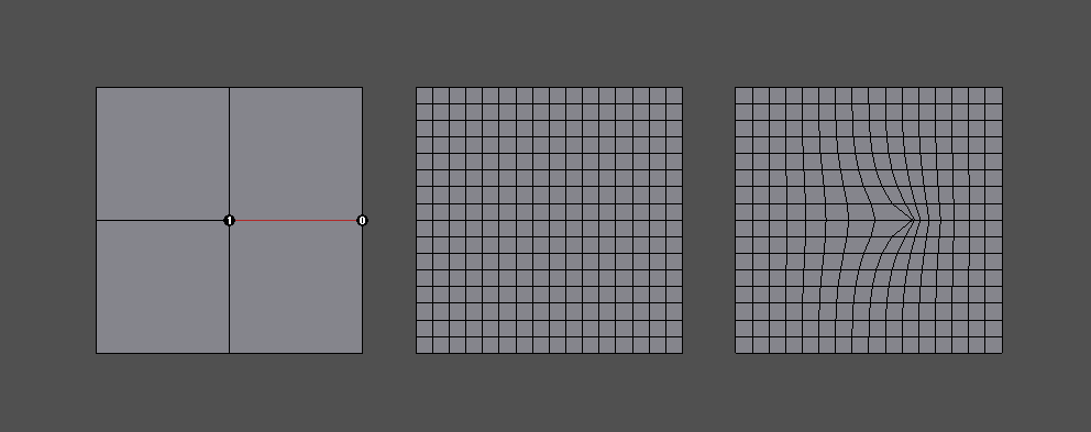
This example shows a simple regular XY grid on the left with an interior sharp edge creating a dart vertex in the center. With no asymmetry in the vertices, the sharpness has no asymmetric affect and the XY vertex interpolation on the immediate right shows the regular grid expected from refinement. On the far right is the UV interpolation from Hbr, which exhibits distortion around the center dart vertex.
The second discrepancy occurs with interpolation involving any fractional sharpness values. Hbr effectively ignores any fractional sharpness value in its face-varying interpolation. So edges of vertices with sharpness of say 2.5, will be treated as though their sharpness is 2.0 when face-varying values are interpolated. Similarly, any non-zero sharpness value less than 1.0 is treated as zero by truncation and so is essentially ignored.
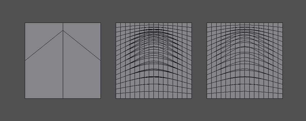
This example shows an asymmetric 2x2 grid of quads on the left with the center vertex progressively sharpened from 0.5 to 1.0. The three cases of the vertex smooth and sharpened are superimposed on the immediate right to display the three distinct interpolation results. On the far right the interpolation from Hbr displays the same three cases, but only two are visibly distinct -- the sharpness of 0.5 being treated the same as if it were 0.0.
Both of these cases are corrected in OpenSubdiv 3.0. Smooth face-varying interpolation in the presence of creasing should match the expected behavior of the vertex interpolation, except where the face-varying topology is explicitly made to differ.
The Chaikin Creasing Method
At least two discrepancies are know to exist between the implementations of Hbr in RenderMan and OpenSubdiv 3.0:
- Use of Chaikin creasing with boundaries or infinitely sharp edges
- Subtle shape differences due to Hbr's use of "predictive sharpness"
Fortunately, this feature was only recently added to Hbr and RenderMan and is little used, so it is expected these differences will have little impact.
The first discrepancy is mentioned briefly in the previous section on compatibility between OpenSubdiv 2.x and 3.0. A conscious decision was made to change the averaging of sharpness values involving infinitely sharp edges in order to make results more predictable and favorable. The effects can be seen comparing the regression shape "catmark_chaikin2".
The second is more subtle and results from an oversight within Hbr's implementation that is not easily corrected.
When determining what subdivision rule to apply from one level to the next, the sharpness values at the next level must be known in order to determine whether or not a transition between differing rules is required. If the rule at the next level differs from the previous, a combination of the two is applied. Such a change results from the sharpness values of one or more edges (or the vertex itself) decaying to zero.
Rather than compute the sharpness values at the next level accurately, Hbr "predicts" it by simply subtracting 1.0 from it, as is done with the uniform creasing method, and it bases decisions on that predicted result. This does not work for Chaikin though. A sharpness value less than 1.0 may not decay to 0 if it is averaged with neighboring sharpness values greater than 1.0, so this sharpness prediction can result in the wrong rule being chosen for the next level.
A typical case would have the subdivision rules for Chaikin creasing transition from Corner to Crease at one level, then from Crease to Smooth at the next. Hbr's predictive creasing might mistakenly detect the transition as Corner to Smooth at one level, then after properly computing the sharpness values for the next level later, from Crease to Smooth for the next. One of the regression shapes ("catmark_chakin1") was disabled from the regression suite because of this effect. The differences in shape that trigger its regression failure were investigated and determined to be the result of this issue.
From observations thus far these differences are subtle but can be noticeable.
Numerical Precision
Since its inception, OpenSubdiv has sought to produce results that were numerically consistent to RenderMan. A regression suite to ensure a certain level of accuracy was provided to detect any substantial deviation.
At some point in the development of OpenSubdiv, the point was made that numerical accuracy of Hbr could be improved by changing the order of operations and combining the vertex with the lowest coefficient first in one of the subdivision rules. This was applied more thoroughly in the independent implementation of 3.0 (there seemed no reason not to). In most cases the relative magnitudes of the coefficients of subdivision and limit masks is clear so no overhead was necessary to detect them.
At a certain point though, this greater accuracy came in conflict with the regression suite. It turned out that high-valence vertices could not be computed to within the desired tolerances set within the suite. The summation of many small coefficients for the adjacent vertices first, before the addition of the much larger coefficient for the primary vertex, allowed for the accumulation of precision that was being truncated by adding the much larger coefficient first in the Hbr implementation. With extremely high valence vertices, a difference in magnitude between the most and least significant coefficients of several orders of magnitude is likely, and that has a significant impact on the single-precision floating point computations.
The improved accuracy of OpenSubdiv 3.0 can reach a magnitude that will not go undetected. Whether or not this can lead to visual artifacts is unclear.