FAR Overview
Feature Adaptive Representation (Far)
Far is the primary API layer for processing client-supplied mesh data into subdivided surfaces.
The Far interface may be used directly and also may be used to prepare mesh data for further processing by Osd.
The two main aspects of the subdivision process are Topology Refinement and Primvar Refinement.
Topology Refinement
Topology refinement is the process of splitting the mesh topology according to the specified subdivison rules to generate new topological vertices, edges, and faces. This process is purely topological and does not depend on the speciific values of any primvar data (point positions, etc).
Topology refinement can be either uniform or adaptive, where extraordinary features are automatically isolated (see feature adaptive subdivision).
The Far topology classes present a public interface for the refinement functionality provided in Vtr,
The main classes in Far related to topology refinement are:
| TopologyRefiner | A class encapsulating mesh refinement. |
| TopologyLevel | A class representing one level of refinement within a TopologyRefiner. |
| TopologyRefinerFactory<MESH> | A factory class template specialized in terms of the application's mesh representation used to construct TopologyRefiner instances. |
Primvar Refinement
Primvar refinement is the process of computing values for primvar data (points, colors, normals, texture coordinates, etc) by applying weights determined by the specified subdivision rules. There are many advantages gained by distinguishing between topology refinement and primvar interpolation including the ability to apply a single static topological refinement to multiple primvar instances or to different animated primvar time samples.
Far supports methods to refine primvar data at the locations of topological vertices and at arbitrary locations on the subdivision limit surface.
The main classes in Far related to primvar refinement are:
| PrimvarRefiner | A class implementing refinement of primvar data at the locations of topological vertices. |
| PatchTable | A representation of the refined surface topology that can be used for efficient evaluation of primvar data at arbitrary locations. |
| StencilTable | A representation of refinement weights suitable for efficient parallel processing of primvar refinement. |
| LimitStencilTable | A representation of refinement weights suitable for efficient parallel processing of primvar refinement at arbitrary limit surface locations. |
Far::TopologyRefiner
TopologyRefiner is the building block for many other useful classes in Far. It performs refinement of an arbitrary mesh and provides access to the refined mesh topology. It can be used for primvar refinement directly using PrimvarRefiner or indirectly by being used to create a stencil table, or a patch table, etc.
TopologyRefiner provides the public refinement methods RefineUniform() and RefineAdapative() which perform refinement operations using Vtr. TopologyRefiner provides access to the refined topology via TopologyLevel instances.
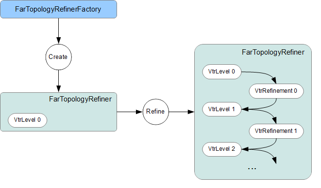
Far::TopologyRefinerFactory
Consistent with other classes in Far, instances of TopologyRefiner are created by a factory class -- in this case Far::TopologyRefinerFactory.
Here we outline several approaches for converting mesh topology into the required Far::TopologyRefiner. Additional documentation is provided with the Far::TopologyRefinerFactory<MESH> class template used by all, and each has a concrete example provided in one of the tutorials or in the Far code itself.
There are three ways to create TopologyRefiners
- use the existing TopologyRefinerFactory<TopologyDescriptor> with a populated instance of TopologyDescriptor
- specialize TopologyRefinerFactory<class MESH> for more efficient conversion, using only face-vertex information
- fully specialize TopologyRefinerFactor<class MESH> for most control over conversion
Use the Far::TopologyDescriptor
Far::TopologyDescriptor is a simple struct that can be initialized to refer to raw mesh topology information -- primarily a face-vertex list -- and then passed to a provided factory class to create a TopologyRefiner from each. Topologically, the minimal requirement consists of:
- the number of vertices and faces of the mesh
- an array containing the number of vertices per face
- an array containing the vertices assigned to each face
These last two define one of the six topological relations that are needed internally by Vtr, but this one relation is sufficient to construct the rest. Additional members are available to assign sharpness values per edge and/or vertex, hole tags to faces, or to define multiple sets (channels) of face-varying data.
Almost all of the Far tutorials (i.e. tutorials/far/tutorial_*) illustrate use of the TopologyDescriptor and its factory for creating TopologyRefiners, i.e. TopologyRefinerFactory<TopologyDescriptor>.
For situations when users have raw mesh data and have not yet constructed a boundary representation of their own, it is hoped that this will suffice. Options have even been provided to indicate that raw topology information has been defined in a left-hand winding order and the factory will handle the conversion to right-hand (counter-clockwise) winding on-the-fly to avoid unnecessary data duplication.
Custom Factory for Face Vertices
If the nature of the TopologyDescriptor's data expectations is not helpful, and so conversion to large temporary arrays would be necessary to properly make use of it, it may be worth writing a custom factory.
Specialization of TopologyRefinerFactory<class MESH> should be done with care as the goal here is to maximize the performance of the conversion and so minimize overhead due to runtime validation. The template provides the high-level construction of the required topology vectors of the underlying Vtr.
There are two ways to write such a factory: provide only the face-vertex information for topology and let the factory infer all edges and other relationships, or provide the complete edge list and all other topological relationships directly. The latter is considerably more involved and described in a following section.
The definition of TopologyRefinerFactory<TopologyDescriptor> provides a clear and complete example of constructing a TopologyRefiner with minimal topology information, i.e. the face-vertex list. The class template TopologyRefinerFactory<MESH> documents the needs here and the TopologyDescriptor instantiation and specialization should illustrate that.
Custom Factory for Direct Conversion
Fully specializing a factory for direct conversion is needed only for those requiring ultimate control and is not generally recommended. It is recommended that one of the previous two methods initially be used to convert your mesh topology into a TopologyRefiner. If the conversion performance is critical, or significant enough to warrant improvement, then it is worth writing a factory for full topological conversion.
Writing a custom factory requires the specification/specialization of two methods with the following purpose:
- specify the sizes of topological data so that vectors can be pre-allocated
- assign the topological data to the newly allocated vectors
As noted above, the assumption here is that the client's boundary-rep knows best how to retrieve the data that we require most efficiently. After the factory class gathers sizing information and allocates appropriate memory, the factory provides the client with locations of the appropriate tables to be populated (using the same Array classes and interface used to access the tables). The client is expected to load a complete topological description along with additional optional data, i.e.:
- the six topological relations required by Vtr, oriented when manifold
- sharpness values for edges and/or vertices (optional)
- additional tags related to the components, e.g. holes (optional)
- values-per-face for face-varying channels (optional)
This approach requires dealing directly with edges, unlike the other two. In order to convert edges into a TopologyRefiner's representation, the edges need to be expressed as a collection of known size N -- each of which is referred to directly by indices [0,N-1]. This can be awkward for representations such as half-edge or quad-edge that do not treat the instance of an edge uniquely.
Particular care is also necessary when representing non-manifold features. The previous two approaches will construct non-manifold features as required from the face-vertex list -- dealing with degenerate edges and other non-manifold features as encountered. When directly translating full topology it is necessary to tag non-manifold features, and also to ensure that certain edge relationships are satisfied in their presence. More details are available with the assembly methods of the factory class template.
While there is plenty of opportunity for user error here, that is no different from any other conversion process. Given that Far controls the construction process through the Factory class, we do have ample opportunity to insert runtime validation, and to vary that level of validation at any time on an instance of the Factory. The factory does provide run-time validation on the topology constructed that can be used for debugging purposes.
A common base class has been created for the factory class, i.e.:
template <class MESH>
class TopologyRefinerFactory : public TopologyRefinerFactoryBase
both to provide common code independent of <MESH> and also potentially to protect core code from unwanted specialization.
Far::PrimvarRefiner
PrimvarRefiner supports refinement of arbitrary primvar data at the locations of topological vertices. A PrimvarRefiner accesses topology data directly from a TopologyRefiner.
Different methods are provided to support three different classes of primvar interpolation. These methods may be used to refine primvar data to a specified refinement level.
| Interpolate(...) | Interpolate using vertex weights |
| InterpolateVarying(...) | Interpolate using linear weights |
| InterpolateFaceVarying(...) | Interpolate using face-varying weights |
Additional methods allow primvar data to be interpolated to the final limit surface including the calculation of first derivative tangents.
| Limit(dst) | Interpolate to the limit surface using vertex weights |
| Limit(dst, dstTan1, dstTan2) | Interpolate including first derivatives to the limit surface using vertex weights |
| LimitFaceVarying(...) | Interpolate to the limit surface using face-varying weights |
PrimarRefiner provides a straightforward interface for refining primvar data, but depending on the application use case, it can be more efficient to create and use a StencilTable, or PatchTable, to refine primvar data.
Far::PatchTable
PatchTable is the collection of patches derived from the refined faces of a particular mesh topology.
This collection is created using Far::PatchTableFactory from an instance of Far::TopologyRefiner after refinement has been applied.
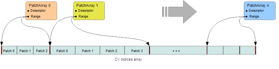
Patch Arrays
The PatchTable is organized into patch arrays. All patches in each array have the same type except for face-varying patch arrays which may have a mix of regular and irregular patch types.
The PatchDescriptor provides the fundamental description of a patch, including the number of control points per patch as well as the basis for patch evaluation.
Each patch in the array is associated with a PatchParam which specifies additional information about the individual patch.
Patch Types
The following are the different patch types that can be represented in the PatchTable:
| Patch Type | #CVs | Description |
|---|---|---|
| NON_PATCH | n/a | "Undefined" patch type |
| POINTS | 1 | Points : useful for cage drawing |
| LINES | 2 | Lines : useful for cage drawing |
| QUADS | 4 | Bi-linear quadrilaterals |
| TRIANGLES | 3 | Linear triangles |
| LOOP | 12 | Quartic triangular Box-spline patches |
| REGULAR | 16 | Bi-cubic B-spline patches |
| GREGORY | 4 | Legacy Gregory patches |
| GREGORY_BOUNDARY | 4 | Legacy Gregory Boundary patches |
| GREGORY_BASIS | 20 | Bi-cubic quadrilateral Gregory patches |
| GREGORY_TRIANGLE | 18 | Quartic triangular Gregory patches |
The type of a patch dictates the number of control vertices expected in the table as well as the method used to evaluate values.
Patch Parameterization
Here we describe the encoding of the patch parameterization for quadrilateral patches. The encoding for triangular patches is similar, please see the API documentation of Far::PatchParam for details.
Each patch represents a specific portion of the parametric space of the coarse topological face identified by the PatchParam FaceId. As topological refinement progresses through successive levels, each resulting patch corresponds to a smaller and smaller subdomain of the face. The PatchParam UV origin describes the mapping from the uv domain of the patch to the uv subdomain of the topological face. We encode this uv origin using log2 integer values for compactness and efficiency.
It is important to note that this uv parameterization is the intrinsic parameterization within a given patch or coarse face and is distinct from any client specified face-varying channel data.

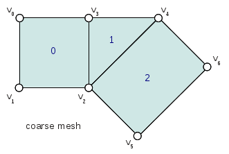
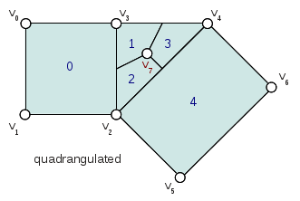
Patches which result from irregular coarse faces (non-quad faces in the Catmark scheme) are offset by the one additional level needed to "quadrangulate" the irregular face. It is the indices of these offset faces that are stored in the PatchParam and used in other classes such as the Far::PatchMap. These offset indices can be identified from the coarse face using the Far::PtexIndices class when needed.
|
|
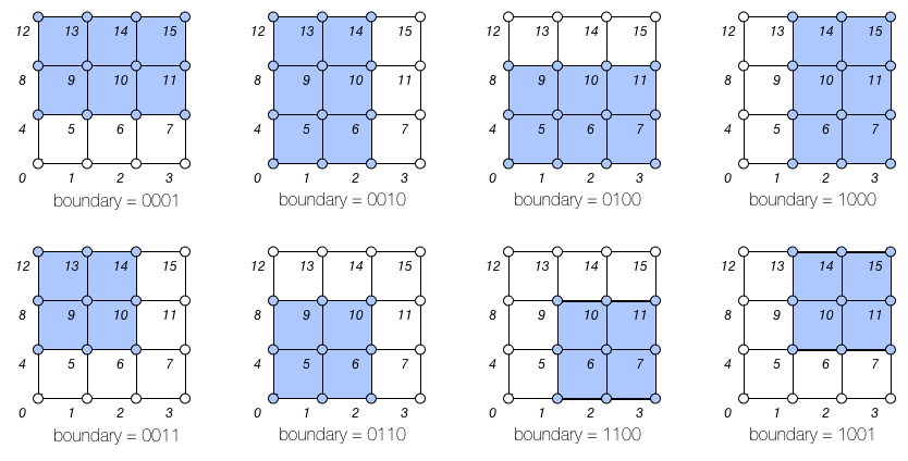
A patch along an interpolated boundary edge is supported by an incomplete sets of control vertices. For consistency, patches in the PatchTable always have a full set of control vertex indices and the PatchParam Boundary bitmask identifies which control vertices are incomplete (the incomplete control vertex indices are assigned values which duplicate the first valid index). Each bit in the boundary bitmask corresponds to one edge of the patch starting from the edge from the first vertex and continuing around the patch. With feature adaptive refinement, regular B-spline basis patches along interpolated boundaries will fall into one of the eight cases (four boundary and four corner) illustrated below:
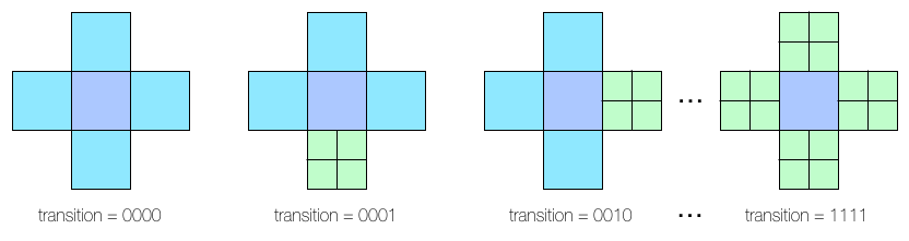
Transition edges occur during feature adaptive refinement where a patch at one level of refinement is adjacent to pairs of patches at the next level of refinement. These T-junctions do not pose a problem when evaluating primvar data on patches, but they must be taken into consideration when tessellating patches (e.g. while drawing) in order to avoid cracks. The PatchParam Transition bitmask identifies the transition edges of a patch. Each bit in the bitmask corresponds to one edge of the patch just like the encoding of boundary edges.
After refining an arbitrary mesh, any of the 16 possible transition edge configurations might occur. The method of handling transition edges is delegated to patch drawing code.
Single-Crease Patches
Using single-crease patches allows a mesh with creases to be represented with many fewer patches than would be needed otherwise. A single-crease patch is a variation of a regular BSpline patch with one additional crease sharpness parameter.
Release Notes (3.x)
Evaluation of single-crease patches is currently only implemented for OSD patch drawing, but we expect to implement support in all of the evaluation code paths for future releases.
Local Points
The control vertices represented by a PatchTable are primarily refined points, i.e. points which result from applying the subdivision scheme uniformly or adaptively to the points of the coarse mesh. However, the final patches generated from irregular faces, e.g. patches incident on an extraordinary vertex might have a representation which requires additional local points.
Legacy Gregory Patches
Using Gregory patches to approximate the surface at the final patches generated from irregular faces is an alternative representation which does not require any additional local points to be computed. Instead, when Legacy Gregory patches are used, the PatchTable must also have an alternative representation of the mesh topology encoded as a vertex valence table and a quad offsets table.
Far::StencilTable
The base container for stencil data is the StencilTable class. As with most other Far entities, it has an associated StencilTableFactory that requires a TopologyRefiner:
Advantages
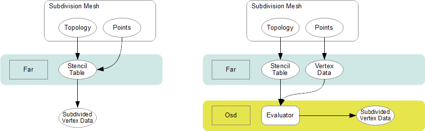
Stencils are used to factorize the interpolation calculations that subdivision schema apply to vertices of smooth surfaces. If the topology being subdivided remains constant, factorizing the subdivision weights into stencils during a pre-compute pass yields substantial amortizations at run-time when re-posing the control cage.
Factorizing the subdivision weights also allows to express each subdivided vertex as a weighted sum of vertices from the control cage. This step effectively removes any data inter-dependency between subdivided vertices : the computations of subdivision interpolation can be applied to each vertex in parallel without any barriers or constraint. The Osd classes leverage these properties by exploiting CPU and GPU parallelism.
Principles
Iterative subdivision algorithms converge towards the limit surface by successively refining the vertices of the coarse control cage. Each successive iteration interpolates the new vertices by applying polynomial weights to a basis of supporting vertices.
The interpolation calculations for any given vertex can be broken down into sequences of multiply-add operations applied to the supporting vertices. Stencil table encodes a factorization of these weighted sums : each stencils is created by combining the list of control vertices from the 1-ring.
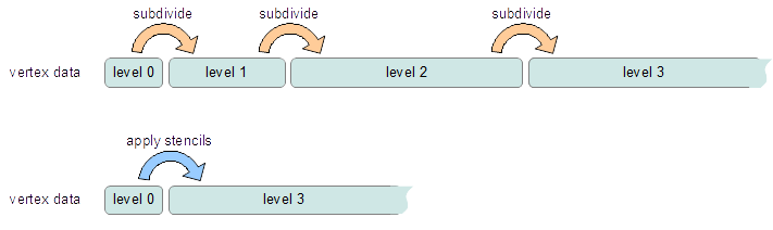
With iterative subdivision, each refinement step is dependent upon the previous subdivision step being completed, and a substantial number of steps may be required in order approximate the limit : each subdivision step incurs an O(4n) growing amount of computations.
Instead, once the weights of the contributing coarse control vertices for a given refined vertex have been factorized, it is possible to apply the stencil and directly obtain the interpolated vertex data without having to process the data for the intermediate refinement levels.
Cascading Stencils
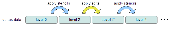
Client-code can control the amount of factorization of the stencils : the tables can be generated with contributions all the way from a basis of coarse vertices, or reduced only to contributions from vertices from the previous level of refinement.
The latter mode allows client-code to access and insert modifications to the vertex data at set refinement levels -- creating what are often referred to as hierarchical edits. Once the edits have been applied by the client-code, another set of stencils can be used to smooth the vertex data to a higher level of refinement.
See implementation details, see the Far cascading stencil tutorial
Limit Stencils
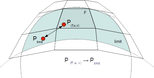
Stencil tables can be trivially extended from discrete subdivided vertices to arbitrary locations on the limit surface. Aside from extraordinary points, every location on the limit surface can be expressed as a closed-form weighted average of a set of coarse control vertices from the 1-ring surrounding the face.
The weight accumulation process is similar : the control cage is adaptively subdivided around extraordinary locations. A stencil is then generated for each limit location simply by factorizing the bi-cubic Bspline patch weights over those of the contributing basis of control-vertices.
The use of bi-cubic patches also allows the accumulation of analytical derivatives, so limit stencils carry a set of weights for tangent vectors.
Once the stencil table has been generated, limit stencils are the most direct and efficient method of evaluation of specific locations on the limit of a subdivision surface, starting from the coarse vertices of the control cage.
Also: just as discrete stencils, limit stencils that are factorized from coarse control vertices do not have inter-dependencies and can be evaluated in parallel.
For implementation details, see the glStencilViewer code example.
Sample Location On Extraordinary Faces
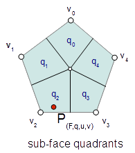
Each stencil is associated with a singular parametric location on the coarse mesh. The parametric location is defined as face location and local [0.0 - 1.0] (u,v) triplet:
In the case of face that are not quads, a parametric sub-face quadrant needs to be identified. This can be done either explicitly or implicitly by using the unique ptex face indices for instance.
Code example
When the control vertices (controlPoints) move in space, the limit locations can be very efficiently recomputed simply by applying the blending weights to the series of coarse control vertices:
class StencilType {
public:

    void Clear() {
        memset( &x, 0, sizeof(StencilType));
    }

    void AddWithWeight( StencilType const & cv, float weight  ) {
        x += cv.x * weight;
        y += cv.y * weight;
        z += cv.z * weight;
    }

    float x,y,z;
};

std::vector<StencilType> controlPoints,
                         points,
                         utan,
                         vtan;

// Update points by applying stencils
controlStencils.UpdateValues<StencilType>( &controlPoints[0], &points[0] );

// Update tangents by applying derivative stencils
controlStencils.UpdateDerivs<StencilType>( &controlPoints[0], &utan[0], &vtan[0] );